Saturday, November 28, 2009

Ingrown Stomach Hair On Men

electronic transistor

electronic pendulum (perhaps more correctly - electro - mechanical) will introduce our young designer in the issue of gravity and the pendulum. May give rise to the construction of a fairly accurate clock. (See the "New Toys" J. Wojciechowski)

instructions for building:
  • electrical system is very simple - a schema
  • coil: two sections (excitation and labor) approximately 2000 conjunction DNE 0.1 and about 200 - 300 zw. DNE 0.15 - 0.2,
  • pendulum with a length of several centimeters with neodymium magnet with a diameter of about 20 - 30 mm - a thickness of 5 - 15 mm,
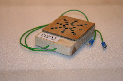
  • to the system (the collector circuit) are included in the LED and the speaker - speaker emits sounds deceptively like the ticking of the clock machanicznego - 20k potentiometer adjust the intensity and pitch, and "momentum" of the pendulum.

Ułożyskowanie that szpilkach wykonanych śrubki M3 pracujących ze w wywierconych wgłębieniach that poprzecznych płaskowniczkach.


Mocowanie wahadła


Wahadło o całkowitej długości 280 mm ma częstotliwość  wahań 1Hz. Na dole wahadła zamocowana jest nagwintowana tuleja żelazna wkręcana na śrubę wciśniętą w 4 mm rurkę mosiężną (umożliwia to regulację długości wahadła). Do tulejki przymocowany jest magnes 18x10 mm


new items with ME - and the speaker coil pendulum

Tuesday, November 24, 2009

Fedex Away On Vacation


Another complementary set of ME: bezkomutatorowy electric motor is a transistor famously - educational, but its power is sufficient to drive the mechanical toys.

The design allows for experimentation:
  • apply power transistor (eg, BD 355) greatly increases the power of an electric motor,
  • no-load (Full load) transistor ASY34 is still cold, light engine load makes it begins to heat up strongly,
  • 20K potentiometer is used to determine the excitation voltage (setting the operating point of the transistor) and smoothly regulates the turnover
  • power transistor (especially cooled ) allows you to bear the power supply to at least 12V, thereby increasing the power and speed, can be used
  • PNP and NPN transistors - pay attention to the polarity of the power
  • for more experienced engine makes it possible to experiment with other systems control: for example, by using thyristors,
  • course, our engine works "in reverse" - can operate as a generator: for example, connect the work coil LED.


construction few notes:
  • pay particular attention to the balance of the rotor and the correct glue magnets on the axis - the engine reaches a very large volume (of the order of tens of thousands) and the centrifugal force can cause disruption of the rotor!
  • engine should not be installed (set) on the board used to lay magnetic circuits e - a distortion which causes sheet on the table will prevent the engine performance
  • from this because we avoid the construction of any portion of ferromagnetic materials - ferrous metal screws that hold the rotor bearings b. affect adversely on his work - best to use brass screws.
Note:
Tiny motor (unfortunately) requires you to manually start : potentiometer is set to "0" and just
; touches the rotor to move.
If the engine does not want to work must change the polarity of the coil excitation.

Wednesday, November 18, 2009

Mobile Doughnut Trailers

ENGINE LED Blinker NE 555


"High school of driving" for a young designer electronics is integrated circuits. We can start from the popular NE 555
LED blinking with frequency depending on the electrolytic capacitor and resistor regulated. In many of the 4.7k resistor can be enabled or thermistor photoresistor. The system will be felt - respectively to light and temperature.
"Going" in integrated circuits requires the implementation of the corresponding module, part of the accepted "philosophy" mounting systems. The module mount stand into the U.S. - this will allow the use of different circuits - such as it look like? Photo below.

Tuesday, November 17, 2009

Can You Recover From Intersitial Cystitis

Generator mcz


mcz simple generator, whose frequency depends on the intensity of light falling on the photoresistor. In place of photoresistor thermistor can be used - the system will be sensitive to temperature changes.

Monday, November 16, 2009

How To Get Gameshark On The Gpsphone

ALARM light-controlled loop


genius (because extremely simple) access security system, windows, land etc. This system works for me has been 5 years without any oversight - power. Instead I used a loop connected to reed in series: the entry gate and the gates of the grounds. Reed are kept in "closed" by a small neodymium magnets mounted in the respective miejscach.Oddzielny loop system secures the perimeter and the roof (after which one could freely enter the house). Yes, it happened: he went to the roof of a cat and broke the loop, but it was once every 5 years! If the alarm system also includes a dog, a cat problem does not occur.
can be used for the experiments matrix ME (as below), but for practical purposes a proven system you can do separately. Current consumption - lesser, calculated in mikroamperach.


Sunday, November 15, 2009

How To Make Disney Leather Bracelet

YOUNG ELEKTRONIK - a set of educational

young electronics - a set of electronic components to allow for self-construction of simple systems for complete beginners in the field of children.

set of characteristics:

- Electronic components - cubes of hardwood (Tekstolit, hard rubber, plastic) containing elements of real, screws and nuts used for joining the system and (under) a magnet providing mounting element on the array assembly. Most ankle elements have a dimension of 20x40x6mm.

- Nailboard A4 size - plywood 3 - 4 mm, is glued on top of sheet iron (ie zinc) 0.3 - 0.5 mm - all painted or covered with colored paper.

- connecting tubes - a maximum of flexible insulated copper cable (about 0.5 mm) connectors oczkowymi completed. I recommend a very flexible cord LIFY - 0.50 mm. At the beginning of just about 20 episodes of 10 cm and 5 - 10 intervals of 20 cm.

- Installation Schemes - A4 sheet of paper with rozrysowanymi outlines the elements and connections between them. Card is wearing the foil is placed on the mounting plate, and on a piece of chipboard elements.

- Attaching and connecting elements - mount with magnets seems to be an optimal solution. Fitting is permanent and any place. Neodymium magnets round (groszowy expenditure) with a diameter of 10 mm and a height of 4 mm are adequate. For some components (antenna, battery, capacitor are mounted on the two magnets. Many variants of combining elements of the simplest and at the same time ensuring the sustainability of a screw connection - connector. Such a merger at the time the strain the patience of some of the young designer, but you can survive it! Alternative radio systems, or other socket type socket assemblies - plug do not work, because in place of the one screw (which can connect up to 4 cables) would have to use 3 - 4 such outlet - an average of 6 - 9 sockets to the element x 25 - 50 items! It is noteworthy that the length of the screws protruding from the ankle - should be fit for the two nuts and four connectors - should be about 15 mm.

- Scope - practically not limited in relation to what little interest in the constructor.

set of elements

Basic (for starters) version is aimed at constructing a simple radio receivers: detektorowych, a - dwutranzystorowych, reactionary, etc. Set includes ferrite antenna - input circuit calculated on receipt of long waves. At this point it opens up the possibility of modifying the first: choosing the appropriate number of turns or coils constructed a new entrance, we can experiment in the receipt of various other frequencies.


Educational Issues:

kit allows introduction of the young, several years of consumer electronics brand in the affairs of the basic: a simple power supply circuit bulbs, LED with a switch and a potentiometer, buzzer, etc. A valuable complement to the set may be a simple measuring instrument (preferably analog). After mastering the basic concepts of electricity and electronics, we can accustom the young designer to carry out practical arrangements with the use of printed circuit boards. Another advantage of the set, it is possible to verify the functioning of systems before it is mounted on the PCB.
design module is transparent - our milusiński not blindly combines cubes with unknown contents, but take note of the appearance of electronic components and methods of their incorporation in the system.

list of the factors used in the present set of "start":
  1. Transistors: ASY 34 - pnp, mcz - recovery from old electronic equipment. You can of course be used successfully and often with better results in later generations of transistors.
  2. LED - any Germans - Blade.
  3. LED - any - 2 pcs.
  4. Capacitors - 100P, 1n, 10n, 680n, 1 - 10 - 100 - 1000 micro.
  5. Resistors - 10ohm, 1k, 3k, 7,5 k, 10k, 50k, 100k.
  6. Potentiometers - 4.7k, 47k.
  7. Buzzer - 12V.
  8. Power - 4 AA batteries.
  9. Headphones - 2 channel radio
  10. ferrite antenna - bar 10 x 140 mm. Coil input circuit: 6 sections of 30 zw. 0.2 mm DNE (better WCZ faces.) From Lay off after the first 30 zw. Reaction coil: 30 zw. shifted to the ferrite rod.
  11. variable capacitor - any receiver with the scope of medium and long term. Is indicated for the unit comprising a capacitor in the VHF range. The kit is used czterosekcyjny capacitor: two sections of 40 pF, a 360 pF and a 300pF.


few patterns to get started:


NOTE:

all systems are checked before publication VIRTUALLY!


Sample execution (the next will be published in future posts in the category of Young ELEKTRONIK - educational kit) :


A - Receiver detektorowy - 3 stages of submission


Postcard from redrawn a model - diagram on the board assembly.


In the second stage we select and arrange the elements of the receiver in place.


Now simply combine elements of cables, headphones on his ears and turning slowly looking capacitor station. In the case of this receiver condition for success is good grounding and antenna from 1920 to 1930 m.


B - Receiver with first transistor


NOTE:
the diagram is missing the connection assembly with a coil of variable capacitor input circuit - the picture of the assembled pipe is visible.




Saturday, November 14, 2009

Ryming Birthday Invites

LED Blinker - another variant of the reaction


Another version of the LED blinker. It should be noted the resistor 1 M - governs the frequency of flashing and scope of this regulation is quite limited. A preliminary forerunner can do to replace it with your fingers.

Wednesday, November 11, 2009

Were To Play Pokemon Crystal Online

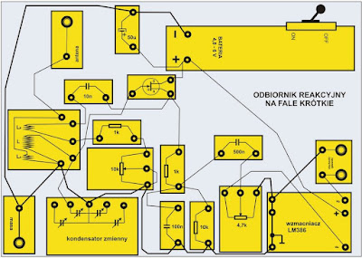
short wave receiver


Another receiver is a receiver set to strengthen the so-called direct response. It is characterized by much higher sensitivity than previously presented in the ME. His submission requires several new elements:
- Antenna module,
- such as field-effect transistor BF 245,
- a few resistors and capacitors (according to the schema.)

Notes construction and start-up:
- as in most construction kit MK value of the items are not critical and the 10k potentiometer for example, can successfully replace the 20k potentiometer, as is the capacitors,
- in the absence of response (excitation of the system), replace the coil connection Circuit reaction
- tuning depends on the initial setting of the radio frequency variable capacitor - bringing the potentiometer to arouse the receiver (squeal in the headphones) - light "withdrawal" from the excitation and the tuning capacitor to the receiving station.
Details of the construction of coils are shown in the respective photographs. Carcass with a diameter of 31 mm is made from a piece of plastic tube and inserted the installation of a resin socket drilled in the wooden podstace. Wire - o, 5 mm DNE.


Monday, November 9, 2009

Denise Milani's Breast Milk

Amplifier LM 386 mcz the


proposed amplifier is a module in the set of Young Electronics (ME), and greatly expands the possibilities to experiment, especially in the field of radio engineering. Is constructed as a separate module connected to the output of the receiver, eg detektorowego. At the amplifier output can be used in speaker or headphones of any resistance. The elements are not critical values, for example, instead of 220 micro-capacitor can be successfully used 100 micro.
If the amplifier has been an issue, it should be blocked for Power + to ground capacitor 50 - 100 microfarads.